標題: 基于TMS320F28027的微弱電壓測量源程序與Proteus仿真 [打印本頁]
作者: banbanshu 時間: 2021-2-7 14:26
標題: 基于TMS320F28027的微弱電壓測量源程序與Proteus仿真
基于TMS320F28027芯片的微弱電壓信號測量,熟練掌握DSP開發環境CCS軟件以及Proteus電路設計軟件,掌握微弱電壓的測量方式,掌握TMS320F28027芯片的基本IO操作、中斷方式、ADC功能的使用,進一步了解DSP系統的特點。
基于TMS320F28027芯片的微弱電壓信號測量方案包括如下幾部分:
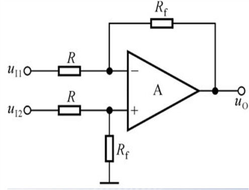
為了便于對微弱電壓(2*(10-3)*sin(100pi*t))進行測量,設計運算放大電路對微弱電壓進行放大處理,使得電壓變為0~3.2V,電路設計如下:
電壓計算公式:Vout=Rf/R*(u11-u12);
(2)基于TMS320F28027的電壓信號采集及轉換
TMS320F28027的ADC功能:
1.12位雙采樣保持電路。
2.同時采樣和序列采樣方式。
3.全范圍電壓輸入,0V到3.3V固定,或者VREFLO到VREFHI可調。
4.系統時鐘全頻運行,無需分頻。
5.16輸入通道。
6.16個SOC配置,設置觸發,采樣窗口,通道。
7.16個獨立保存轉換結果的結果寄存器。
8.多觸發源。
9.9個靈活的PIE中斷
ADC采集電壓計算公式如下:
Vol=(AdcResult.ADCRESULT0)/4096*3.3;
(3)電壓的動態顯示
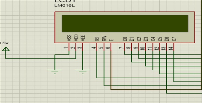
測量到電壓后進行顯示,本次實驗采用LM016L型號LCD顯示器進行電壓顯示。
引腳接口說明:
第1腳:VSS為地電源。
第2腳:VDD接5V正電源。
第3腳:VL為液晶顯示器對比度調整端,接正電源時對比度最弱,接地時對比度最高。
第4腳:RS為寄存器選擇,高電平時選擇數據寄存器、低電平時選擇指令寄存器。
第5腳:R/W為讀寫信號線,高電平時進行讀操作,低電平時進行寫操作。當RS和R/W共同為低電平時可以寫入指令或者顯示地址,當RS為低電平R/W為高電平時可以讀忙信號,當RS為高電平R/W為低電平時可以寫入數據。
第6腳:E端為使能端,當E端由高電平跳變成低電平時,液晶模塊執行命令。
第7~14腳:D0~D7為8位雙向數據線。
LM016L接線如下所示:
指令如下所示:
芯片時序表如下:
| | | | |
| | RS=L,R/W=L,D0—D7=指令碼,E=高脈沖 | | |
| | | | |
| | RS=H,R/W=L,D0—D7=數據,E=高脈沖 | | |
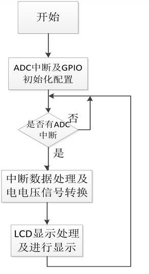
(2)程序流程圖
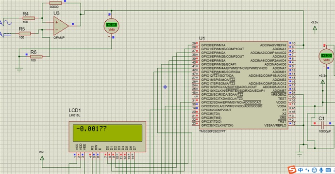
電路設計如下:
程序如下所示:
在Proteus軟件進行仿真,仿真結果截圖如下:
LCD顯示小數點后5位,輸入正弦電壓幅值為0.002,顯示精度為百分之一。

51hei.png (8.65 KB, 下載次數: 75)
下載附件
2021-2-7 15:47 上傳
全部資料51hei下載地址:
作者: wanhao 時間: 2022-11-2 20:02
軟件不全,能發全嗎
作者: 281523048 時間: 2023-5-5 11:41
資料很全,很好 謝謝樓主
謝謝樓主
作者: kk17328 時間: 2023-5-16 22:45
protuse竟然可以仿真DSP,666
作者: TTQ001 時間: 2023-5-17 08:58
如果測量的電壓非常小,低至幾毫伏,則可以使用儀器級運算放大器。
作者: ZHAOBAO511 時間: 2023-10-16 16:14
您好,能否把能編譯工程發一下,謝謝。
作者: ZHAOBAO511 時間: 2023-10-16 16:27
您好,這個例程很好,能否給個能編譯的整套源碼?
作者: 202202lll 時間: 2025-1-6 18:01
資料很好,謝謝樓主
| 歡迎光臨 (http://www.zg4o1577.cn/bbs/) |
Powered by Discuz! X3.1 |
主站蜘蛛池模板:
久久91av|
欧美久久一区二区
|
韩国av网站在线观看
|
欧美日韩中文字幕在线播放
|
中文字幕一区二区三区在线观看
|
久久福利电影
|
日本免费在线观看视频
|
日本一区二区在线视频
|
丝袜一区二区三区
|
亚洲欧美激情精品一区二区
|
欧美国产日韩一区二区三区
|
国产精品国产成人国产三级
|
日韩三级
|
国产一二区视频
|
性做久久久久久免费观看欧美
|
国产一区欧美一区
|
亚洲乱码一区二区
|
亚洲欧美成人在线
|
日韩精品在线观看一区二区三区
|
久草视频网站
|
国产日韩精品一区
|
羞羞视频在线网站观看
|
天堂在线www
|
www.日本在线播放
|
久久综合一区
|
a级在线免费视频
|
男插女下体视频
|
亚洲视频一区在线观看
|
日本网站免费在线观看
|
欧美极品在线观看
|
欧美黄色性生活视频
|
国产一卡二卡三卡
|
久久精品一级
|
亚洲美女在线视频
|
久久精品亚洲
|
欧美五月婷婷
|
国产精品久久久久久久久久妞妞
|
久久久久久久久99
|
成人h电影在线观看
|
国产一区二区精品在线
|
久草新在线|

 Proteus仿真與ccs代碼.7z
(5.99 MB, 下載次數: 97)
Proteus仿真與ccs代碼.7z
(5.99 MB, 下載次數: 97)
 基于TMS320F28027的微弱電壓測量.doc
(453.5 KB, 下載次數: 37)
基于TMS320F28027的微弱電壓測量.doc
(453.5 KB, 下載次數: 37)