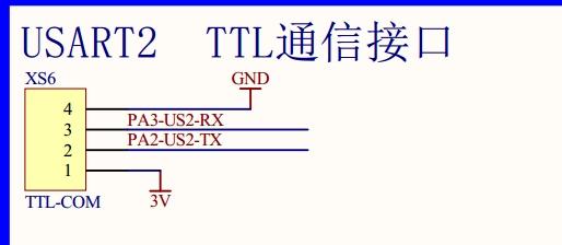
原理圖:
頭文件及完整例程下載:http://www.zg4o1577.cn/f/stm32標準例程庫函數.rar
程序分析:
int main(void)
{
uint8_t a=0;
/* System Clocks Configuration */
RCC_Configuration(); //系統時鐘設置
/*嵌套向量中斷控制器
說明了USARTx搶占優先級級別0(最多1位) ,和子優先級級別0(最多7位) */
NVIC_Configuration(); //中斷源配置
/*對控制LED指示燈的IO口進行了初始化,將端口配置為推挽上拉輸出,口線速度為50Mhz。PA2,PA2端口復用為串口2的TX,RX。
在配置某個口線時,首先應對它所在的端口的時鐘進行使能。否則無法配置成功,由于用到了端口B, 因此要對這個端口的時鐘
進行使能,同時由于用到復用IO口功能用于配置串口。因此還要使能AFIO(復用功能IO)時鐘。*/
GPIO_Configuration(); //端口初始化
USART_Config(USART2); //串口1初始化
USART_OUT(USART2,"****(C) COPYRIGHT 2013 奮斗嵌入式開發工作室 *******\r\n"); //向串口1發送開機字符。
USART_OUT(USART2,"* *\r\n");
USART_OUT(USART2,"* 奮斗版STM32開發板 USART2 實驗 *\r\n");
USART_OUT(USART2,"* *\r\n");
USART_OUT(USART2,"* 以HEX模式輸入一串數據,以16進制0d 0a作為結束 *\r\n");
USART_OUT(USART2,"* *\r\n");
USART_OUT(USART2,"* 奮斗STM32論壇:www.ourstm.net *\r\n");
USART_OUT(USART2,"* *\r\n");
USART_OUT(USART2,"***************************************************\r\n");
USART_OUT(USART2,"\r\n");
USART_OUT(USART2,"\r\n");
while (1)
{
if(rec_f==1){ //判斷是否收到一幀有效數據
rec_f=0;
USART_OUT(USART2,"\r\n您發送的信息為: \r\n");
USART_OUT(USART2,&TxBuffer1[0]);
if(a==0) {GPIO_SetBits(GPIOB, GPIO_Pin_5); a=1;} //LED1 V6(V3板) V2(MINI板) 明暗閃爍
else {GPIO_ResetBits(GPIOB, GPIO_Pin_5);a=0; }
}
}
}
時鐘初始化RCC_APB2Periph_GPIOA ()
void RCC_Configuration(void)
{
SystemInit();
RCC_APB2PeriphClockCmd( RCC_APB2Periph_GPIOA | RCC_APB2Periph_GPIOB |RCC_APB2Periph_GPIOD |
RCC_APB2Periph_AFIO , ENABLE);
RCC_APB1PeriphClockCmd( RCC_APB1Periph_USART2, ENABLE);
}
中斷向量初始化,分組NVIC_PriorityGroup_0 ,初始化USART2_IRQn
void NVIC_Configuration(void)
{
/* 結構聲明*/
NVIC_InitTypeDef NVIC_InitStructure;
/* Configure the NVIC Preemption Priority Bits */
/* Configure one bit for preemption priority */
/* 優先級組 說明了搶占優先級所用的位數,和子優先級所用的位數 在這里是1, 7 */
NVIC_PriorityGroupConfig(NVIC_PriorityGroup_0);
NVIC_InitStructure.NVIC_IRQChannel = USART2_IRQn; //設置串口2中斷
NVIC_InitStructure.NVIC_IRQChannelPreemptionPriority = 0; //搶占優先級 0
NVIC_InitStructure.NVIC_IRQChannelSubPriority = 0; //子優先級為0
NVIC_InitStructure.NVIC_IRQChannelCmd = ENABLE; //使能
NVIC_Init(&NVIC_InitStructure);
}
GPIO初始化
void GPIO_Configuration(void)
{
GPIO_InitStructure.GPIO_Pin = GPIO_Pin_5; //LED1控制--PB5
GPIO_InitStructure.GPIO_Mode = GPIO_Mode_Out_PP; //推挽輸出
GPIO_InitStructure.GPIO_Speed = GPIO_Speed_50MHz;
GPIO_Init(GPIOB, &GPIO_InitStructure);
GPIO_InitStructure.GPIO_Pin = GPIO_Pin_12; //RS485輸入輸出控制
GPIO_InitStructure.GPIO_Mode = GPIO_Mode_Out_PP; //推挽輸出
GPIO_InitStructure.GPIO_Speed = GPIO_Speed_50MHz;
GPIO_Init(GPIOD, &GPIO_InitStructure);
GPIO_SetBits(GPIOD, GPIO_Pin_12); //RS485輸出模式 禁止485輸入
GPIO_InitStructure.GPIO_Pin = GPIO_Pin_2; //USART2 TX
GPIO_InitStructure.GPIO_Mode = GPIO_Mode_AF_PP; //復用推挽輸出
GPIO_Init(GPIOA, &GPIO_InitStructure); //A端口
GPIO_InitStructure.GPIO_Pin = GPIO_Pin_3; //USART2 RX
GPIO_InitStructure.GPIO_Mode = GPIO_Mode_IN_FLOATING; //復用開漏輸入
GPIO_Init(GPIOA, &GPIO_InitStructure); //A端口
GPIO_InitStructure.GPIO_Pin = GPIO_Pin_13; //LCD背光控制
GPIO_InitStructure.GPIO_Speed = GPIO_Speed_50MHz;
GPIO_InitStructure.GPIO_Mode = GPIO_Mode_Out_PP;
GPIO_Init(GPIOD, &GPIO_InitStructure);
GPIO_ResetBits(GPIOD, GPIO_Pin_13); //LCD背光關閉
}
void USART_Config(USART_TypeDef* USARTx){
USART_InitStructure.USART_BaudRate = 115200; //速率115200bps
USART_InitStructure.USART_WordLength = USART_WordLength_8b; //數據位8位
USART_InitStructure.USART_StopBits = USART_StopBits_1; //停止位1位
USART_InitStructure.USART_Parity = USART_Parity_No; //無校驗位
USART_InitStructure.USART_HardwareFlowControl = USART_HardwareFlowControl_None; //無硬件流控
USART_InitStructure.USART_Mode = USART_Mode_Rx | USART_Mode_Tx; //收發模式
/* Configure USARTx */
USART_Init(USARTx, &USART_InitStructure); //配置串口參數函數
/* Enable USARTx Receive and Transmit interrupts */
USART_ITConfig(USART2, USART_IT_RXNE, ENABLE); //使能接收中斷
USART_ITConfig(USART2, USART_IT_TXE, ENABLE); //使能發送緩沖空中斷
/* Enable the USARTx */
USART_Cmd(USART2, ENABLE);
}
